

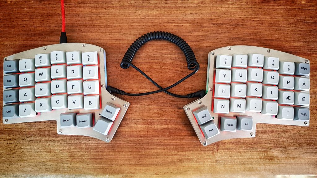
I have been working a a few builds lately and one of them has ended up becoming my daily driver at work right away. I am talking about the Iris split ortho keyboard from keeb.io.
The keyboard was actually one I won in a charity raffle on/r/mk last christmas, but it has just been sitting on my desk in pieces due to lack of time.
I finally got around to build it and it turned out better than I hoped for.
Building the thing
My Iris kit consisted of two pcb’s, stainless steel top and bottom plates and acrylic white middle layers. Besides this It needs the usual gang of two Pro micros, a lot of resistors, diodes, LEDs etc.
Full list of parts:
- 2 sets of plates (top+bottom for each hand)
- 2 Iris PCBs
- 2 TRRS jacks
- 1 TRRS cable
- 2 reset switches
- 4 4.7kΩ resistors
- 2 used for I2C
- 1 used for LED support on left half
- 1 used for LED support on right half
- 56 1N4148 diodes – (I used through-hole but smd is supported)
- 56 470Ω resistors (for LED backlight – I actually ended up using 510 ohm instead)
- 56 LEDs (I used red 4x3x2 LEDs)
- 2 N-channel MOSFETs (for LED control)
- WS2812B RGB LED Strip with 10 LEDs and cut in two (for underglow)
- 2 Pro Micros
- 56 switches (I used Cherry MX clears)
Note: I preprogrammed my two pro-micros with QMK firmware before soldering them on. This is always a good idea to do to make sure the pro micro actually work (can be programmed)
The layout I used for the firmware can be found here: My Github Repo
Build steps in pictures
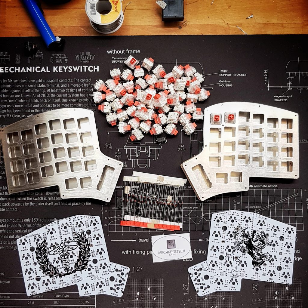
Ready to start – I initially wanted to use kailh box royal burnt orange, but they do not play well with through-switch LEDs and I did not have any smd leds in stock.
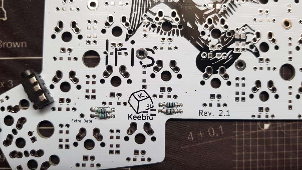
Resistors for I2C and leds
Adding through-hole resistors row by row
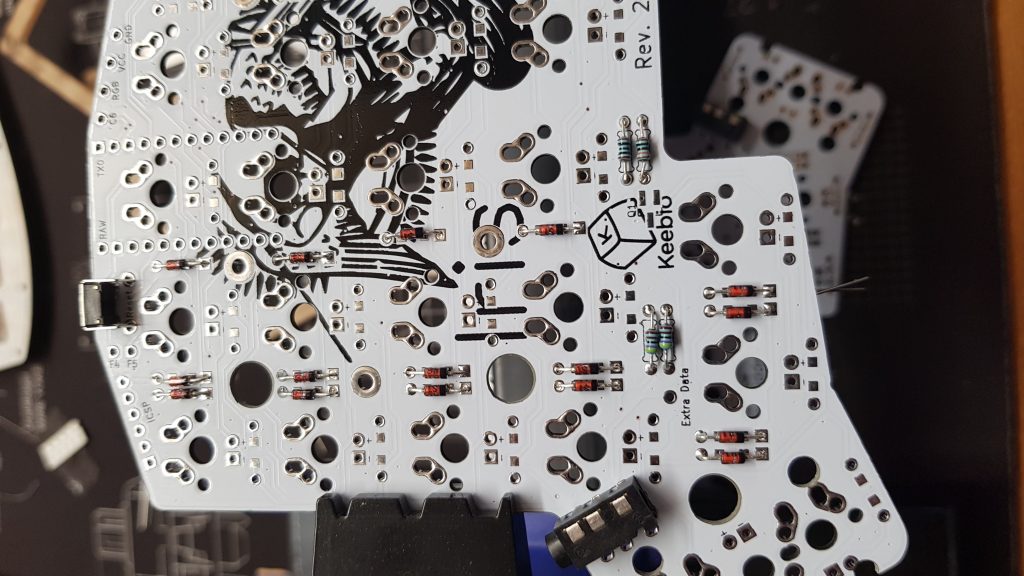
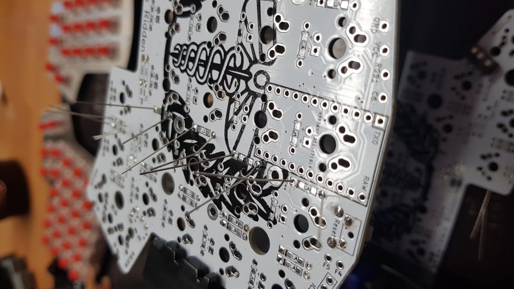
Diodes all ligning up in the same direction. I chose to have black end in direction towards the user. Just make sure all are in the same direction
Left hand (master) with TRRS plug and reset switch on. Notice that I have both resistors and diodes on the bottom side.
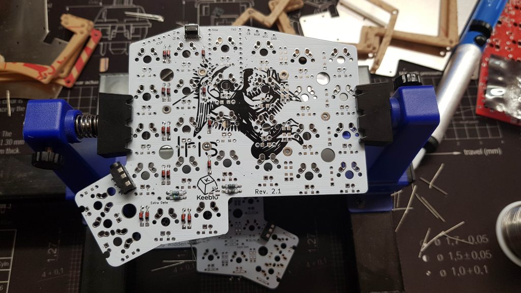
Right hand with diodes, TRRS and reset button.
Sockets for the pro-micro added to the right hand. REMEMBER: left hand pro micro needs to be be chip-down and right hand needs to be chip-up.
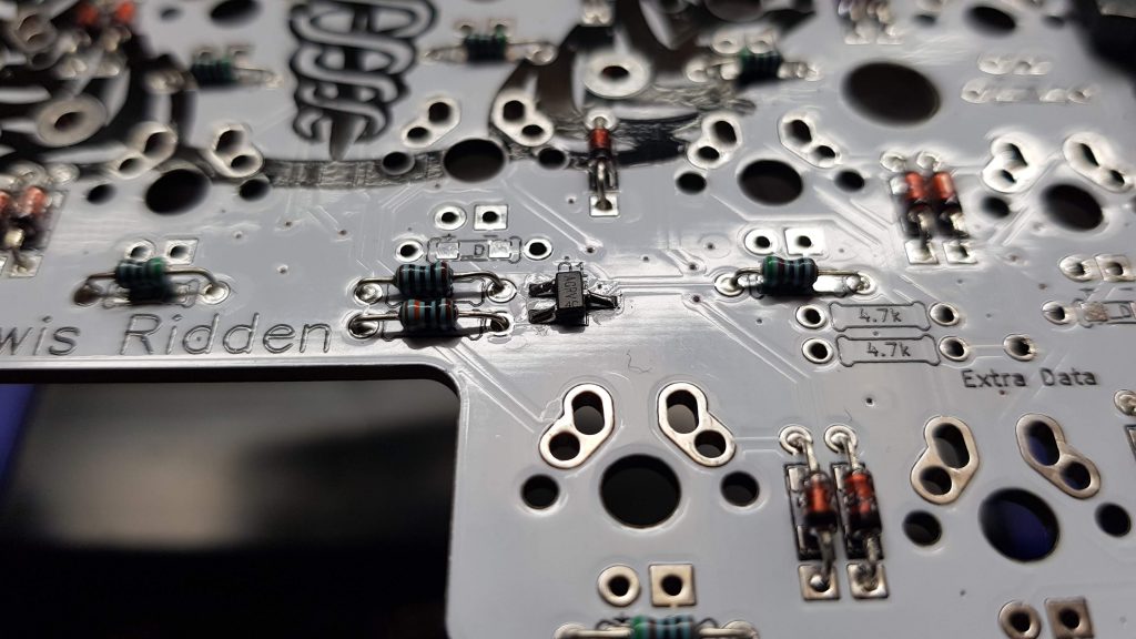
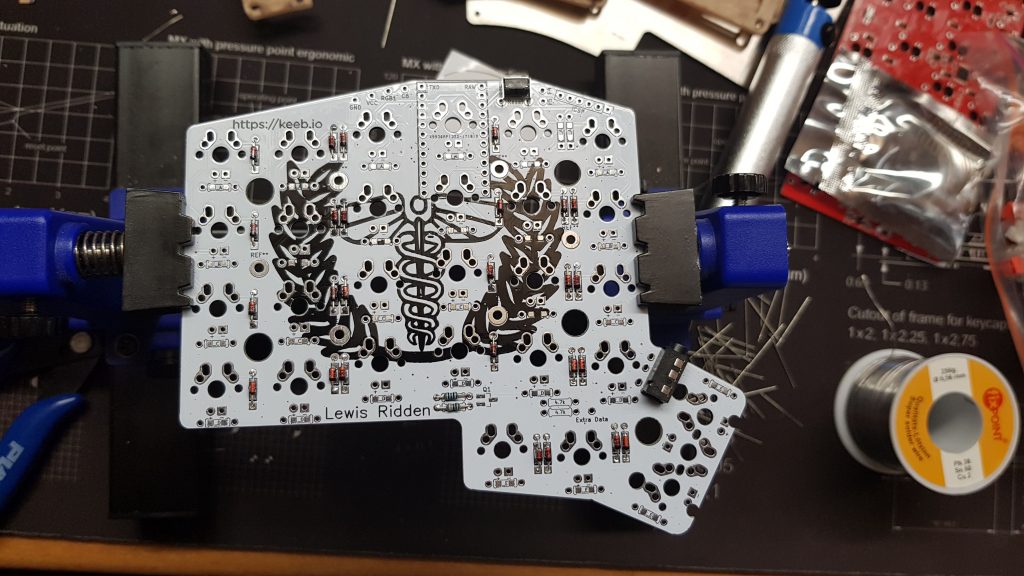
Mosfet added to the right hand. It needs to go on both hands while the I2C resistors only need to go on left hand (master).
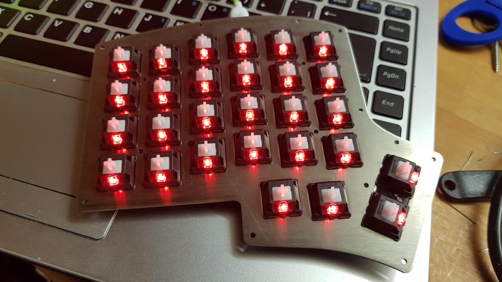
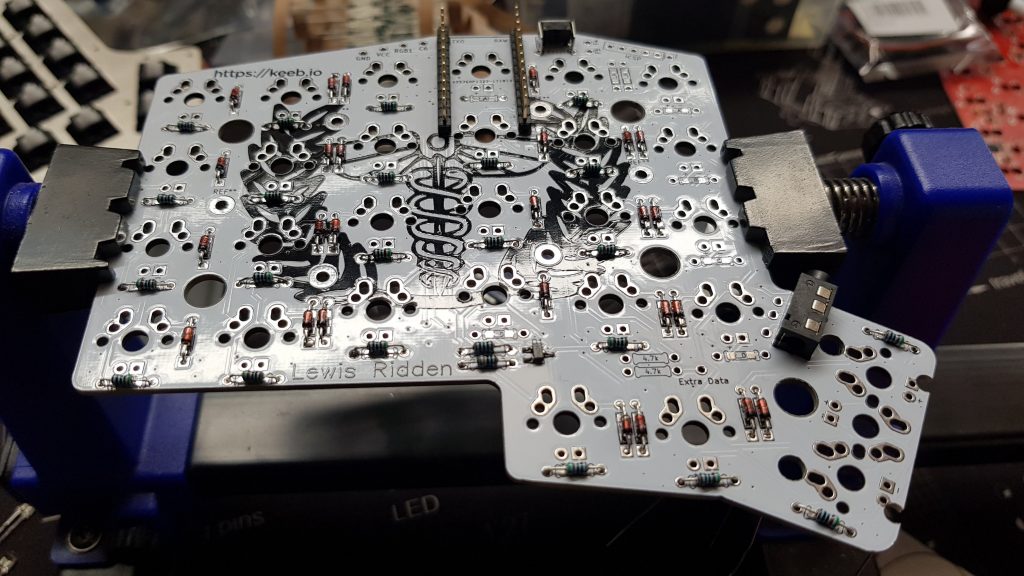
Left hand ready (except for underglow).
Final Result with keycaps
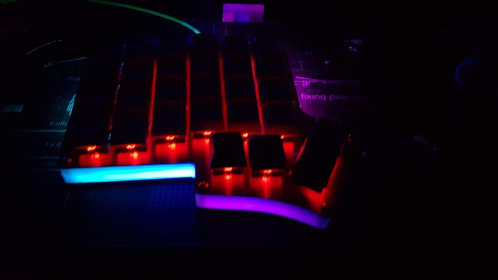
RGB Underglow in action
